Lesson Objective
By the end of this lesson, you should be able to:
- Understand Shifts - Explain logical and arithmetic binary shifts
- Apply Bitwise Operations - Use AND, OR, XOR, and NOT for bit manipulation
- Work with Masks - Create and apply bit masks to manipulate specific bits
- Perform Bit Operations - Extract, clear, set, and toggle subsets of bits
- Recognize Applications - Identify real-world uses like subnet masking
Student Login
Access exclusive lesson resources, notes, and materials.
Introduction to Bit Manipulation
Bit Manipulation is a fundamental low-level programming technique that allows direct control of individual bits within binary data. This is a key advantage of assembly language and is essential for systems programming, hardware control, and performance optimization.
Two Primary Methods of Bit Manipulation
1. Shift Instructions: Move bits left or right within a binary number
- Logical shifts (left and right)
- Arithmetic shifts (right only)
- Used for multiplication and division by powers of 2
2. Logical Instructions with Masks: Use Boolean operations to modify specific bits
- AND, OR, XOR, NOT operations
- Bit masks to target specific bits
- Used to extract, clear, set, or toggle bits
Logical Binary Shifts
A logical binary shift moves all bits in a binary number left or right. This is a very efficient way for a computer to perform multiplication or division by powers of 2.
Logical Left Shift (Multiply)
Each left shift multiplies the number by 2. Bits move to the left, a '0' is added at the rightmost position, and the leftmost bit is discarded if it goes beyond the fixed number of bits.
| Shifts | Bit 7 | Bit 6 | Bit 5 | Bit 4 | Bit 3 | Bit 2 | Bit 1 | Bit 0 | Decimal | Effect |
|---|---|---|---|---|---|---|---|---|---|---|
| 0 (Original) | 0 | 0 | 0 | 0 | 1 | 0 | 0 | 0 | 8 | - |
| 1 Left Shift | 0 | 0 | 0 | 1 | 0 | 0 | 0 | 0 | 16 | ×2 |
| 2 Left Shifts | 0 | 0 | 1 | 0 | 0 | 0 | 0 | 0 | 32 | ×4 |
| 3 Left Shifts | 0 | 1 | 0 | 0 | 0 | 0 | 0 | 0 | 64 | ×8 |
When a binary number is shifted left logically, the most significant bit (MSB) is discarded and a 0 is shifted in to its place. The carry bit is set to the value of the MSB that was discarded.
| Carry Bit | 1 | 1 | 1 | 1 | 0 | 1 | 0 | 0 | ||
| Carry Bit | 1 | 1 | 1 | 1 | 0 | 1 | 0 | 0 | 0 |
Note: Logical shifts won’t work with a two’s complement negative number. Logical shifts only work with Unsigned Binary. They do not preserve the sign for two's complement negative numbers.
Logical Right Shift (Divide)
Each right shift divides the number by 2 (integer division, remainder is discarded). Bits move to the right, a '0' is added at the leftmost position, and the rightmost bit is discarded.
| Shifts | Bit 7 | Bit 6 | Bit 5 | Bit 4 | Bit 3 | Bit 2 | Bit 1 | Bit 0 | Decimal | Effect |
|---|---|---|---|---|---|---|---|---|---|---|
| 0 (Original) | 0 | 0 | 0 | 1 | 0 | 0 | 0 | 0 | 16 | - |
| 1 Right Shift | 0 | 0 | 0 | 0 | 1 | 0 | 0 | 0 | 8 | ÷2 |
| 2 Right Shifts | 0 | 0 | 0 | 0 | 0 | 1 | 0 | 0 | 4 | ÷4 |
| 3 Right Shifts | 0 | 0 | 0 | 0 | 0 | 0 | 1 | 0 | 2 | ÷8 |
When a binary number is shifted right logically, the least significant bit (LSB) is discarded and a 0 is shifted in to its place. The carry bit is set to the value of the LSB that was discarded.
| 1 | 1 | 1 | 1 | 0 | 1 | 0 | 0 | Carry Bit | ||
| 0 | 1 | 1 | 1 | 1 | 0 | 1 | 0 | 0 | Carry Bit |
Note: Logical shifts always fill the vacated bit position with a 0. For signed numbers (using two's complement), computers often use an arithmetic shift, which behaves differently.
Arithmetic Shifts?
A Logical Shift applies to both left and right shifts. In a left shift, bits are moved left, and the vacated least significant bit (LSB) is filled with a zero. In a right shift, bits are moved right, and the vacated MSB is also filled with a zero. Logical shifts treat the binary number as a sequence of bits without considering its signedness.
Arithmetic Shifts only applies to right shifts. Similar to a left logical shift, bits are moved right. However, the vacated MSB is filled with a copy of the original MSB (sign bit). This preserves the sign of the number during the shift. Arithmetic shifts are crucial for signed number operations, especially when dealing with negative numbers in two's complement representation.
Arithmetic Shift Right
| 1 | 1 | 1 | 1 | 0 | 1 | 0 | 0 | Carry Bit | ||
| 1 | 1 | 1 | 1 | 1 | 0 | 1 | 0 | 0 | Carry Bit |
Underflow and Overflow
Overflow occurs when the result of a calculation is too large to be held in the number of bits allocated.
For example, adding two integers in an 8-bit byte (ignore the sign bit). The result 260 cannot be stored in 8 bits (max 255), causing overflow.
| 1 | 1 | 1 | |||||||
| 1 | 0 | 0 | 0 | 0 | 0 | 0 | 1 | 129 | |
| + | 1 | 0 | 0 | 0 | 0 | 0 | 1 | 1 | 131 |
| 1 | 0 | 0 | 0 | 0 | 0 | 1 | 0 | 0 | 260 |
Underflow occurs when a number is too small to be represented in the number of bits allocated.
It may occur if a very small number is divided by a number greater than 1.
Example: Shows a 8 bit binary number shifting one space to the right. The fractional part (.5) is lost when using integer shifts, representing a form of underflow where precision is too fine for the representation.
| 1 | 0 | 0 | 0 | 0 | 0 | 0 | 1 | ||
| ÷2 | 0 | 1 | 0 | 0 | 0 | 0 | 0 | 0 | 1 |
Advertisement.
Bitwise Operations and Masks
Logic Gates and Truth Tables
Electronic circuits called logic gates perform Boolean functions on binary inputs. These gates form the basis of all digital logic circuits and correspond directly to bitwise operations in programming.
Truth Tables show the results of Boolean equations from all possible combinations of inputs.
- Used to show all possible outcomes from Boolean equations
- Also used for logic gate diagrams
- Systematically lists every possible input combination and its corresponding output
AND Gate
For an AND Gate the output is TRUE only if ALL inputs are TRUE.
Symbol:
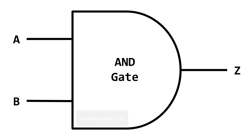
Truth Table:
| A | B | Z |
|---|---|---|
| 0 | 0 | 0 |
| 0 | 1 | 0 |
| 1 | 0 | 0 |
| 1 | 1 | 1 |
Boolean Algebra Notation:
- Z = A ∧ B
- Z = A . B
- Z = A AND B
- Z = AB
OR Gate
For an OR Gate the output is TRUE if EITHER or ALL inputs are TRUE.
Symbol:
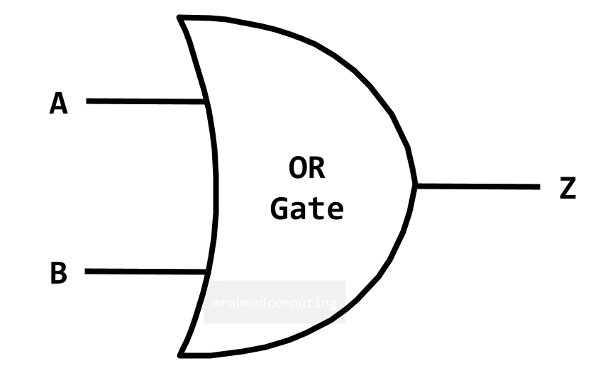
Truth Table:
| A | B | Z |
|---|---|---|
| 0 | 0 | 0 |
| 0 | 1 | 1 |
| 1 | 0 | 1 |
| 1 | 1 | 1 |
Boolean Algebra Notation:
- Z = A ∨ B
- Z = A + B
- Z = A OR B
NOT Gate
For a NOT Gate the output is the OPPOSITE (inverse) of the input.
Symbol:
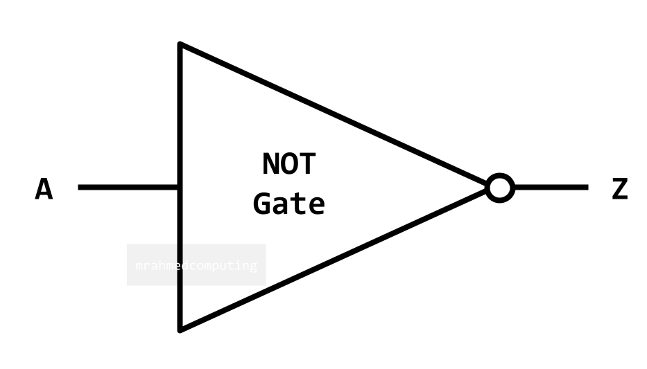
Truth Table:
| A | Z |
|---|---|
| 0 | 1 |
| 1 | 0 |
Boolean Algebra Notation:
- Z = ¬A
- Z = Ā
- Z = NOT(A)
- Z = A'
XOR Gate (Exclusive OR)
For an XOR Gate the output is TRUE if only ONE input is TRUE.
Symbol:
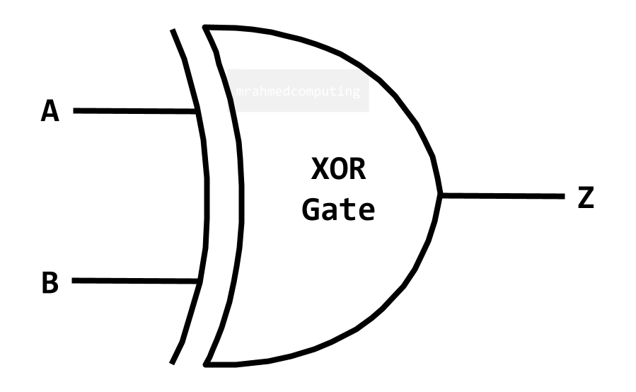
Truth Table:
| A | B | Z |
|---|---|---|
| 0 | 0 | 0 |
| 0 | 1 | 1 |
| 1 | 0 | 1 |
| 1 | 1 | 0 |
Boolean Algebra Notation:
- Z = A ⊻ B
- Z = A ⊕ B
- Z = A XOR B
Advertisement.
Boolean Logic and Masks
The instructions AND, OR and XOR can be summarised in the table below:
| AND | OR | XOR | |
|---|---|---|---|
| Input A | 1010 | 1110 | 1001 |
| Input B | 1100 | 1100 | 1100 |
| Result | 1000 | 1110 | 0101 |
Input B is a mask, which in combination with the Boolean operator, will set, clear or toggle the input bits. Masking allows you to isolate, extract and edit a sequence of bits.
Bitwise - AND
The AND operator can be used to clear a particular set of bits, leaving the other bits unchanged.
To clear the rightmost 4 bits. We would use the Mask (11110000) with the AND operator.
| Input A | 0 | 1 | 1 | 1 | 0 | 1 | 0 | 0 |
| Input B (Mask) | 1 | 1 | 1 | 1 | 0 | 0 | 0 | 0 |
| Output | 0 | 1 | 1 | 1 | 0 | 0 | 0 | 0 |
Bitwise - OR
The OR operator may be used to set a particular bit, leaving the other bits unchanged. To set the bit 1, 4 and 8 (furthest left bit is bit 1). We would use the Mask (10010001) with the OR operator.
| Input A | 0 | 1 | 1 | 1 | 0 | 1 | 0 | 0 |
| Input B (Mask) | 1 | 0 | 0 | 1 | 0 | 0 | 0 | 1 |
| Output | 1 | 1 | 1 | 1 | 0 | 1 | 0 | 1 |
Bitwise - XOR
The XOR operator can be used to toggle a particular bit, leaving the other bits unchanged. To toggle the rightmost 4 bits. Leaving the leftmost 4 bits unchanged. We would use the Mask (00001111) with the XOR operator.
| Input A | 0 | 1 | 1 | 1 | 0 | 1 | 0 | 0 |
| Input B (Mask) | 0 | 0 | 0 | 0 | 1 | 1 | 1 | 1 |
| Output | 0 | 1 | 1 | 1 | 1 | 0 | 1 | 1 |
Real-World Applications
Subnet Masking in Networking
One of the most practical applications of bit masking is in computer networking, specifically for subnet masking. Network engineers use this technique to:
- Efficiently route traffic across complex networks
- Isolate specific sections of an IP address to distinguish between network and host portions
- Segment networks into smaller, manageable subnetworks
This fundamental concept enables efficient IP address management and forms the backbone of modern network architecture.
Example: IP Address 135.68.1.1/16
The "/16" indicates the first 16 bits represent the network portion.
IP Address in Binary:
| 1 0 0 0 0 1 1 1 | . | 0 1 0 0 0 1 0 0 | . | 0 0 0 0 0 0 0 1 | . | 0 0 0 0 0 0 0 1 |
| 135 | 68 | 1 | 1 |
Subnet Mask: 255.255.0.0
First 16 bits are 1s (network), last 16 bits are 0s (host):
| 1 1 1 1 1 1 1 1 | . | 1 1 1 1 1 1 1 1 | . | 0 0 0 0 0 0 0 0 | . | 0 0 0 0 0 0 0 0 |
| 255 | 255 | 0 | 0 |
When the IP address is ANDed with the subnet mask, the network address is extracted, leaving the host portion cleared. This is fundamental for routing traffic on networks.
Other Common Applications:
- Graphics Programming: Manipulating pixel colors, alpha channels, and image masks
- Embedded Systems: Controlling hardware registers and device flags
- Data Compression: Packing multiple values into single bytes
- Cryptography: Implementing encryption algorithms and hash functions
- Game Development: Efficiently storing game state and permissions
- Database Systems: Implementing bitmap indexes for fast queries
Lesson Summary
- Logical Shifts: Move bits left (multiply by 2) or right (divide by 2) for unsigned numbers
- Arithmetic Shifts: Right shifts that preserve sign bit for signed numbers
- Bitwise AND: Clears bits where mask is 0 - used for extracting/isolating bits
- Bitwise OR: Sets bits where mask is 1 - used for combining bit patterns
- Bitwise XOR: Toggles bits where mask is 1 - used for flipping/inverting bits
- Bit Masks: Binary patterns that determine which bits are affected by operations
- Overflow/Underflow: Occur when results exceed representable range in allocated bits
- Real Applications: Subnet masking, graphics, embedded systems, data compression
- Logic Gates: Hardware implementations of Boolean operations (AND, OR, NOT, XOR)